![]()
XIS Controls Model 600 Event Controller And Totalizer
The E-CAT is a compact Counting and Venue capacity controller hardware device with powerful capabilities rivaling similar computer based software systems at a fraction of their cost. These are but a few features of the touch screen based system:
- 16, 24 or 32 counting inputs. Up to 64 on special request
- Every input is individually programmable for either up or down counting
- Every input is fully buffered – Non contention counting
- 2 levels of password protection and feature configuration
- 4 levels of count based output relays with visual indicators
- 3 programmable count recipes
- 2 auxiliary controllable relays + 2 special state relays
- Remote counter reset as a programmable option
- Venue (ins minus outs), Event & Grand totals in several screen formats
- Totals and configuration parameters are non-volatile.
Terminology & General Operation:
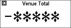
- Venue Total – This is the sum of all ins (up counts) minus all outs (down counts). This counter is capable of registering up to 99,999 counts. It represents the number of patrons currently in the venue, gallery or event confines
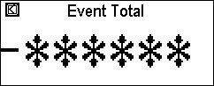
- Event Total – This is the total of only the ins (up counts). This counter is capable of registering up to 999,999 counts. It is possible to know the number of patrons that have visited a particular exhibit yet also know how many are currently inside.
- Grand Total – This is similar to Event Total, only registering entries (ins – up counts). This counter is capable of registering up to 99,999,999 counts. Where the Event Counter might be suitable for the day or week, the Grand Total might be suitable for the life of the exhibit.
-
Counter Limits – Venue and Event counters will roll
over and although will appear to be reset visually they are actually continuing
to record counts. When the Event Counter rolls over, the screen backlight will
begin to flash indicating that a manual reset is required.
- When the Grand Total counter limit is reached the counter is automatically reset to zero.
- Resetting The Venue & Event Counters are done simultaneously and does not affect the Grand Total. Resetting the Grand Total also resets the Venue & Event Totals. All reset operations require a “confirm” action.
-
Switches A, B, C – these are relay outputs that are
controlled by user settable count limits (trip points). They can be separately
set to operate when the “Venue Count” reaches a number that you can select
between 0 and 99,999. Indicators marked A, B & C will change appearance in
accordance with the selected trip points. In addition, the backlight can be
made to change color or stay green when these trip points are reached. When
used with backlight color change. Trip point A causes no color change. Trip
point B causes the backlight to turn
- Up to 3 different sets of trip points can be pre established for switches A, B, & C. These are called “Recipes”. Once setup, these pre-canned recipes may be made user selectable to permit quick changeover of event formats.
- Switches A, B & C may be placed in three different modes: Auto – The output relay will be off if the venue count is below the trip point and on if above the trip point, On – Always “on” regardless of the trip point, Off – Always “off” regardless of the trip point. ABC screen indicators as well as backlight color change are not affected by these manual overrides.
- Switches D & E are manually operated and permit the user to operate the corresponding output relays for whatever additional equipment they wish to control.
- Switch F operates solely on a user settable value for the Event Total. Perhaps you want something to happen automatically or be alerted when a certain number of patrons have passed through the gates.
- 2 additional relays operate when the Venue count is equal to Zero and the other when the Venue count is negative (below zero).
-
There are 3 level of access: Operator, Supervisor and
Administrator. What features available to the Operator & Supervisor and
certain system behaviors are determined by the Administrator under password control.
Operation:
Upon application of power the Splash Screen is displayed.
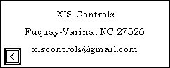
During the 5 second period that this screen is displayed, it is possible to retrieve other information. Pressing the XIS Controls Logo provides you with company contact information.
Or pressing the “Event Totalizer & Capacity Controller” box provides you with system information.
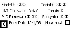
Most of the information here establishes specific factory production information. The “Inputs” field determines how many inputs are enabled for use. Of particular note is the “Encryptor” field. Should you ever forget your Administrator’s password, the factory can recover it for you with this information. The “Heartbeat” indicator determines the health of the PLC. The left facing arrow will return you to the Splash screen. After five seconds at the Splash screen the Main Menu page will be displayed.
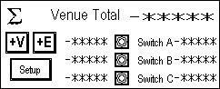
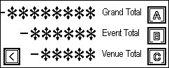
At the top right of this screen is displayed the current Venue Total. On all pages, the number of asterisks indicates the numerical range possible. The lower group of numerical fields and indicators represent: left numerics – The recipe values for switches A, B & C, Indicators – change color when the associate trip point is reached, right numerics – The number of counts remaining to the associated target trip point. In other words, how many more people until the trip point is reached. Be aware that a negative number in this column represents how many entries have been made over the associated trip point.
Pressing the ∑ symbol displays the Summary Page showing Venue, Event, and Grand Totals as well as the status of switches/relays A, B & C. The back arrow takes you to the previous page and always has the same meaning wherever it is encountered.
Pressing the V+ or E+ boxes takes you to the associated large screen of the Venue or Event totals. They are there for convenient viewing from a distance.
Pressing the Setup Box takes you to the Supervisors Screen.
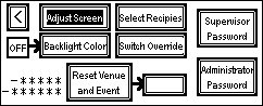
With the exception of the back arrow button, most boxes or press-able buttons can have a light or dark background. A light background usually symbolizes off, not available or not set. A dark background might indicate on, feature available, password unlocked.
- “Adjust Screen” is always available and therefore the background is always dark. Pressing this button will permit the operator to adjust screen brightness and contrast.
- Backlight Color – When the button is dark this may be operated. The on/off box to the left of it indicates if a backlight color change will occur based on trip points (on) or not (off).
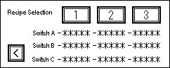
- Select Recipes – When dark, takes you to the screen below. The screen displays the three recipes determined by the Administrator. Pressing one of the three buttons selects that recipe.
- Pressing the Switch override takes you to the screen below. The Administrator has selected access rights to this screen. The access can be selected for the ABC and DE groups separately. The left hand on/off boxes will indicate if operation is permitted on/dark=operable, off/light=locked. These switches may be pre setup and locked in that state under password control. Switches A, B & C have 3 states and may be changed by repeated pressing of the button. They cycle; Auto-Off-On and then repeat. C & D are either On or Off. The buttons change to dark or light when the actual relay is on or off. In addition the current Venue Total is displayed in the lower right corner.
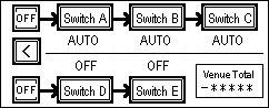
- When dark, pressing the “Reset Venue and Event” buttons on the Supervisor’s screen will cause the small button to the right to turn dark and indicate “Confirm”. Pressing the Confirm button resets both the Venue and Event Totals. After 5 seconds, whether pressed or not, the Confirm option resets. Both Venue (top) and Event (bottom) Totals are displayed to the left of the reset button.
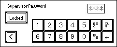
- Pressing the Supervisor’s or Administrator’s Password boxes takes you to the following screens respectively. In either case the Locked/Unlocked button shows the access status for each level of individual. Pressing these buttons when Unlocked is shown will Lock that level of access. In addition the 2 buttons labeled Supervisor’s Password and Administrator’s Password, on the supervisors page, will be either light or dark reflecting Locked or Unlocked. To enter a password, press the numerical field, enter the password with the keypad and press the enter key (bent arrow).
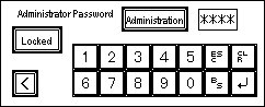
- If the Administrator’s password has been properly entered. The “Administration” button will become dark. Pressing it will take you to the following screen.
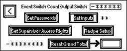
- Since the Administrator has access to all features, all boxes will be dark. The top entry is for Relay F which operates at a point you can select based on the Event Total. Pressing the numeric field takes you to a keyboard screen.
- Pressing “Set Passwords” takes you to the screen below. The current passwords will be shown. Pressing the numeric field will take you to a keyboard screen. Be aware that changing passwords will require you to re-login once you have backed out as far as the Supervisor’s screen. In addition, changing the Administrator’s password immediately cancels the unlocked status of these screens. Do not back out of the “Set Password” screen until you are sure these are the passwords you want and will remember.
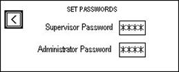
- A special note about passwords: Passwords consist of the password set by the Administrator on the screen above and the password you entered to gain access to an area. When both the pre-set password and the entered access password match, the access status becomes “unlocked”. When you press the button to “lock” access, you essentially set the value of the access password to zero. This is useful you want to grant the Supervisor’s functions and/or Administrator’s functions to the operator. To do this, make the password zero in the appropriate “Set Password” field.
- Pressing “Set Inputs” May take you to the following screens. Depending on the number of active inputs shown to the right of the Set Inputs button, you may or may not have access to configuring all these buttons.
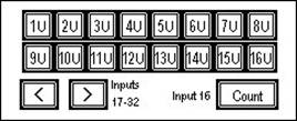
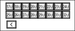
- Pressing any of the input buttons will alternately set the associated input to count either Up or Down, As shown above, all inputs are set to count up. A down counting input would be presented on a dark background with 1D, for example for input 1. Input 16 may be configured as a remote reset for Venue & Event totals only rather than using it as a counting input. This may be useful in an automated presentation theatre where the doors close in response to one of the trip point relays and reopen when the count is zeroed. Whether you can configure all or some of these inputs will be determined by the factory setting.
- Pressing the “Set Supervisor’s Access Rights” button will take you to the following page.
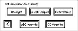
- Pressing any of these buttons assigns access rights to these functions to the Supervisor when he has signed in with his password. The button will have a dark background when the Supervisor’s accessibility has been turned on.
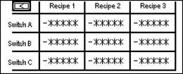
- Pressing “Recipe Setup” takes you to the following screen. Pressing the numerical field in any of the boxes will take you to a keyboard screen permitting you to enter a value for each switch/relay for each recipe.
- On the bottom line of the Administrator’s screen is shown
the current Grand Total. This may be reset to zero by pressing the “Reset
Grand Total” button and then the “Confirm” box. As before the option to confirm
will expire in five seconds.
|
XIS
Controls - Pedestrian Control & Automation Solutions - Engineers,
Innovators
|